Company News & Updates
Advanced Thermal Imaging Technology in Water Damage Detection
October 20, 202524 min read
T
Tyler McClelland· Mitigation Manager, Hudson Valley Region (NY)
Tyler McClelland leads mitigation operations for Advanced DRI across New York's Hudson Valley, directing water, mold, and large-loss response in the field. He holds IICRC Water Restoration Technician (WRT) and Applied Microbial Remediation Technician (AMRT) certifications and a New York State Mold Supervisor certification, and is trained in IRCA hospital safe construction practices recognized by The Joint Commission.
IICRC Water Restoration Technician (WRT), IICRC Applied Microbial Remediation Technician (AMRT), NY State Mold Supervisor Certification, Lead RRP Certification, OSHA Bloodborne Pathogens Training, IRCA Hospital Safe Construction Practices (TJC), Large Loss Mastery Estimating CertifiedLinkedIn
Published October 20, 2025 · Updated May 27, 2026

Expert guide to thermal imaging water damage detection. Learn infrared technology principles, professional methodologies and equipment specifications.
Technical Background and Evolution of Thermal Imaging
Historical Development of Infrared Technology
Thermal imaging technology emerged from military applications in the mid-20th century, with commercial availability beginning in the 1970s. Early systems were cumbersome, expensive, and required significant technical expertise. The adaptation of infrared technology to building diagnostics and water damage assessment accelerated in the 1990s as sensor technology improved and equipment costs decreased. Today's thermal cameras represent sophisticated instruments capable of detecting temperature differentials as small as 0.05°C, making them indispensable tools for professional moisture detection. The evolution from analog to digital thermal imaging fundamentally changed how restoration professionals approach water damage assessment. Modern thermal cameras produce high-resolution digital images with embedded temperature data, enabling precise documentation and analysis. The integration of visible light imaging with thermal data creates reference images that significantly improve interpretation accuracy and client communication.Thermodynamic Principles of Moisture Detection
Thermal imaging water damage detection relies on fundamental thermodynamic principles, particularly the relationship between moisture content and thermal properties of building materials. Water has a significantly higher specific heat capacity than most construction materials—approximately 4.18 kJ/(kg·K) compared to 0.84 kJ/(kg·K) for concrete or 1.21 kJ/(kg·K) for gypsum board. This difference creates detectable temperature variations when materials contain excess moisture. Key Thermal Property Relationships: Heat Transfer Rate: Q = k × A × (ΔT/Δx) Where: Q = Heat transfer rate (W) k = Thermal conductivity (W/m·K) A = Surface area (m²) ΔT = Temperature difference (K) Δx = Material thickness (m) Evaporative Cooling Effect: q = ṁ × hfg Where: q = Cooling rate (W) ṁ = Mass flow rate of evaporation (kg/s) hfg = Latent heat of vaporization (2,257 kJ/kg for water) The evaporative cooling effect is the primary mechanism enabling thermal imaging moisture detection. As water evaporates from wet materials, it absorbs significant thermal energy, creating cooler surface temperatures. This temperature depression typically ranges from 2-8°C depending on ambient conditions, material type, and moisture content. Thermal cameras detect these temperature differentials as distinct thermal patterns.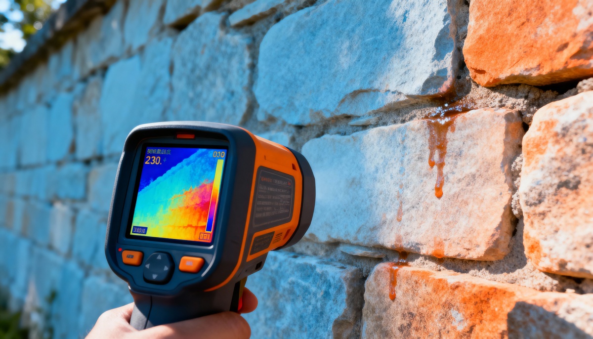
Industry Standards and Protocols
Professional thermal imaging applications in water damage assessment are governed by multiple industry standards. Standard S500 provides guidelines for professional water damage restoration, including documentation requirements that thermal imaging fulfills exceptionally well. Standard S520 addresses mold remediation and emphasizes the importance of comprehensive moisture detection, for which commercial mold removal services increasingly rely on infrared technology. The infrared thermography standards applicable to building diagnostics (Standard 96) establish protocols for equipment calibration, operator qualifications, environmental conditions during surveys, and reporting requirements. These standards specify minimum thermal sensitivity requirements (0.1°C or better), calibration intervals, and documentation formats. Professional restoration contractors must understand and implement these standards to ensure defensible moisture assessments.🔬 Technical Note: Thermal imaging detects surface temperature variations, not moisture directly. Professional interpretation requires understanding the relationship between thermal patterns and subsurface moisture conditions based on material properties, environmental factors, and building construction.
Deep Technical Analysis of Thermal Imaging Systems
Infrared Camera Technology and Specifications
Modern thermal cameras for water damage detection employ uncooled microbolometer sensor arrays that detect infrared radiation in the long-wave spectrum (8-14 μm). These sensors convert infrared radiation into electrical signals, which are processed to create thermal images displaying temperature distributions across surfaces. Understanding key specifications is essential for selecting appropriate equipment and interpreting results accurately.| Specification | Entry-Level | Professional | Advanced | Impact on Water Damage Detection |
|---|---|---|---|---|
| Thermal Sensitivity (NETD) | 0.10°C | 0.05°C | 0.03°C | Ability to detect subtle moisture patterns |
| Infrared Resolution | 160 × 120 pixels | 320 × 240 pixels | 640 × 480 pixels | Spatial detail and accurate boundary definition |
| Temperature Range | -20°C to +250°C | -40°C to +650°C | -40°C to +1200°C | Versatility across applications |
| Accuracy | ±2°C or ±2% | ±1.5°C or ±1.5% | ±1°C or ±1% | Quantitative temperature measurement reliability |
| Field of View | 25° × 19° | 42° × 32° | 56° × 42° | Area coverage efficiency |
Emissivity Considerations in Building Materials
Emissivity—the ratio of radiation emitted by a surface to radiation emitted by a perfect black body at the same temperature—critically affects thermal imaging accuracy. Different building materials exhibit varying emissivity values, and professional thermal imaging requires proper emissivity compensation for accurate temperature measurement.| Material | Emissivity (ε) | Surface Condition Impact | Moisture Detection Considerations |
|---|---|---|---|
| Painted Drywall | 0.90-0.95 | Minimal variation | Excellent thermal imaging target |
| Bare Concrete | 0.85-0.95 | Texture affects reading | Good for moisture detection |
| Wood (unfinished) | 0.80-0.90 | Grain direction affects emissivity | Suitable with proper interpretation |
| Ceramic Tile | 0.90-0.94 | Glaze affects emissivity | Very good thermal stability |
| Polished Metal | 0.05-0.20 | Highly reflective | Unreliable for direct thermal imaging |
| Vinyl Flooring | 0.85-0.95 | Pattern affects uniformity | Good for subsurface moisture detection |
⚙️ Engineering Consideration: Reflective surfaces can create false thermal patterns by reflecting radiation from other sources. Professionals must distinguish between actual temperature variations and reflected thermal energy, particularly when imaging near windows, polished floors, or metallic building components.
Environmental Factors Affecting Thermal Imaging
Environmental conditions significantly influence thermal imaging water damage detection. Understanding these factors enables professionals to optimize survey timing and interpret results accurately: Ambient Temperature Differentials: Thermal imaging requires temperature differentials between wet and dry materials. Optimal conditions occur when ambient temperature differs from the building's thermal equilibrium, typically during heating or cooling cycles. Early morning surveys often provide excellent conditions as building materials equilibrate overnight. For critical situations requiring immediate response, 24-hour emergency services can deploy thermal imaging capabilities at optimal assessment times. Relative Humidity Impact: High relative humidity reduces evaporative cooling rates, diminishing the temperature differential between wet and dry materials. Surveys conducted when relative humidity exceeds 70% may show less distinct thermal patterns. Conversely, low humidity conditions enhance evaporative cooling, creating more pronounced thermal signatures. Air Movement Effects: Air currents accelerate evaporation from wet materials, enhancing the evaporative cooling effect. However, excessive air movement can create non-uniform thermal patterns that complicate interpretation. Professional surveys should document HVAC operation status and airflow patterns. Solar Loading: Direct or recent solar exposure creates thermal patterns unrelated to moisture. Exterior walls, roofs, and areas near windows may show thermal variations from solar heating rather than moisture intrusion. Professionals must schedule surveys to minimize solar loading effects or allow sufficient equilibration time after sunset. Thermal Bridging: Structural elements with different thermal conductivity create temperature patterns that may be confused with moisture. Steel framing, concrete columns, and other structural components often appear cooler than surrounding materials due to thermal bridging, not moisture content.Professional Methodology and Protocols
Systematic Survey Procedures
Professional thermal imaging surveys for water damage assessment follow systematic protocols to ensure comprehensive coverage and reliable results. The methodology integrates thermal imaging with traditional moisture measurement techniques to provide validated moisture mapping that meets the standards required for commercial restoration services. Pre-Survey Preparation:- Equipment calibration verification and battery status confirmation
- Environmental condition documentation (temperature, humidity, barometric pressure)
- Building system status recording (HVAC, dehumidification equipment operation)
- Site-specific considerations identification (building materials, construction type, previous water damage)
- Scope definition and survey pattern planning
- Thermal Reconnaissance: Conduct broad thermal survey of affected areas to identify thermal anomalies indicating potential moisture, which is essential for comprehensive commercial water cleanup and extraction
- Anomaly Documentation: Record thermal images of all identified anomalies with reference photographs and location documentation
- Verification Measurements: Use contact moisture meters to verify moisture content at thermal anomaly locations
- Boundary Mapping: Define moisture extent boundaries using integrated thermal and contact measurement data
- Documentation: Create comprehensive thermal imaging reports with annotated images, temperature measurements, and moisture readings
📊 Data Point: Research indicates that thermal imaging combined with capacitance moisture meter verification provides moisture detection accuracy exceeding 95% when performed by trained professionals under appropriate environmental conditions.
Integration with Traditional Moisture Detection Methods
Thermal imaging excels at rapid, non-invasive moisture detection over large areas, but professional protocols require verification with contact moisture measurement instruments. This integrated approach combines the strengths of multiple technologies:| Detection Method | Primary Strength | Limitations | Role in Integrated Protocol |
|---|---|---|---|
| Thermal Imaging | Rapid large-area scanning, non-invasive | Surface conditions only, requires verification | Initial detection and boundary identification |
| Pin-Type Meters | Direct moisture measurement, material-specific | Invasive, point measurement | Verification of thermal anomalies |
| Non-Invasive Meters | Subsurface reading, non-destructive | Affected by material density and salts | Verification without surface penetration |
| Thermo-Hygrometers | Environmental condition monitoring | Ambient conditions only | Survey condition documentation |
| Moisture Mapping | Comprehensive documentation | Time-intensive | Detailed affected area documentation |
Documentation Standards and Reporting
Professional thermal imaging documentation must meet industry standards for technical accuracy, clarity, and legal defensibility. Comprehensive reports include: Essential Report Components:- Survey date, time, and environmental conditions
- Equipment specifications and calibration status
- Survey methodology and protocols followed
- Thermal images with temperature scales and reference photographs
- Annotated floor plans showing thermal anomaly locations
- Verification moisture readings at thermal anomaly locations
- Temperature and humidity measurements
- Moisture extent boundaries and affected area calculations
- Material identification and construction details
- Interpretations and conclusions with supporting data
Case Study: Commercial Office Building Water Intrusion
Project Overview
A 45,000 square foot, three-story commercial office building experienced suspected water intrusion following a severe storm event. Visible evidence was limited to minor ceiling staining in second-floor offices, but facility management requested comprehensive moisture assessment to identify hidden water migration and prevent potential mold development. Building Specifications:- Construction: Steel frame with brick veneer exterior
- Interior finishes: Painted gypsum board walls, suspended acoustic ceiling tiles
- Flooring: Commercial carpet over concrete slab (second and third floors)
- HVAC: Central air handling units with zone control
- Age: 18 years
Technical Challenges
Several factors complicated traditional moisture assessment:- Large floor area requiring rapid but thorough assessment
- Occupied office spaces limiting access and requiring minimal disruption
- Suspended ceilings concealing water migration paths
- Recent HVAC operation potentially drying visible moisture while leaving concealed areas wet
- Insurance documentation requirements demanding comprehensive affected area mapping
Thermal Imaging Survey Methodology
The assessment team deployed thermal imaging as the primary detection tool, conducting surveys during evening hours when temperature stabilization optimized thermal contrast. Survey conditions included:- Ambient temperature: 22°C
- Relative humidity: 58%
- Barometric pressure: 1013 mbar
- HVAC system: Operational during survey
- Time since precipitation event: 36 hours
| Location | Thermal Anomaly Characteristics | Verified Moisture Content | Extent |
|---|---|---|---|
| Second Floor East Wing | 2.5-4.2°C temperature depression | 18-24% (gypsum board) | 280 sq ft |
| Third Floor Directly Above | 1.8-3.5°C temperature depression | 16-21% (gypsum board) | 180 sq ft |
| Exterior Wall Cavity (East) | 3.2-5.1°C temperature depression | 22-28% (insulation/framing) | 120 linear ft |
| Second Floor Carpet Areas | 1.5-2.8°C temperature depression | 15-19% (carpet/pad) | 340 sq ft |
Critical Findings
Thermal imaging revealed water migration patterns invisible to visual inspection. The thermal data indicated water entered through compromised exterior wall flashing, migrated through wall cavities, and affected three separate areas across two floors. Temperature differentials correlated strongly with verified moisture content measurements (correlation coefficient r = 0.89), validating thermal imaging accuracy. Particularly valuable was the identification of moisture in the exterior wall cavity—an area inaccessible to visual inspection without destructive investigation. Thermal imaging detected the characteristic thermal pattern of wet insulation and framing members, enabling targeted verification and remediation planning.Measured Performance Outcomes
Assessment Efficiency: Thermal imaging survey of 45,000 square feet completed in 4.5 hours, compared to estimated 12-16 hours for traditional probe-based moisture mapping. Time savings: approximately 70%. Detection Accuracy: Thermal imaging identified seven distinct moisture areas; verification confirmed moisture presence in all seven locations with no false positives in sampled areas (n=45 verification points). Documentation Quality: Thermal images with annotated floor plans provided clear, objective documentation accepted without dispute by insurance adjuster, expediting claim processing. Cost Impact: Early detection of concealed moisture prevented estimated secondary damage and enabled focused remediation scope, reducing total project costs.Lessons Learned
- Environmental Timing: Conducting surveys 36-48 hours post-water event provided optimal conditions. Materials retained sufficient moisture for thermal detection while evaporative cooling remained active.
- Verification Protocol: Systematic verification of thermal anomalies with capacitance meters confirmed thermal imaging reliability while providing quantitative data for remediation planning.
- Concealed Space Value: Thermal imaging proved particularly valuable for detecting moisture in inaccessible areas, preventing the need for extensive exploratory demolition.
- Client Communication: Visual thermal images significantly improved client understanding of water damage extent and remediation necessity compared to traditional moisture meter readings alone. This is especially valuable when working with healthcare facilities that require comprehensive documentation and minimal disruption.
- Documentation Standards: Comprehensive thermal imaging reports with reference photographs, annotated floor plans, and verification data satisfied stringent insurance documentation requirements without supplemental investigation.
📊 Data Point: Post-remediation thermal surveys confirmed complete drying in 8.5 days using targeted drying equipment placement informed by initial thermal imaging moisture mapping—approximately 30% faster than typical timeline for similar projects using conventional moisture mapping.
Industry Trends and Future Developments
Advanced Sensor Technology
Thermal imaging technology continues evolving rapidly, with several developments enhancing water damage detection capabilities: Higher Resolution Sensors: New microbolometer arrays achieving 1024 × 768 resolution provide unprecedented spatial detail. Higher resolution enables detection of smaller moisture areas and more precise boundary definition, particularly valuable in complex commercial structures. Enhanced Thermal Sensitivity: Next-generation sensors approaching 0.02°C sensitivity enable detection of increasingly subtle thermal patterns, improving early-stage moisture detection before significant damage occurs. Multi-Spectral Imaging: Integration of thermal and visible light imaging with automated fusion algorithms creates composite images combining thermal data with visual context, improving interpretation accuracy and reducing training requirements.Artificial Intelligence and Automated Analysis
Machine learning algorithms are increasingly applied to thermal imaging analysis for water damage detection. AI-powered systems can:- Automatically identify thermal patterns characteristic of moisture intrusion
- Distinguish between moisture-related thermal anomalies and thermal bridging, solar loading, or other non-moisture factors
- Generate preliminary moisture maps from thermal survey data
- Track moisture reduction during drying operations through sequential thermal image analysis
- Flag anomalies requiring professional interpretation
Integration with Building Information Modeling
Forward-thinking restoration firms are integrating thermal imaging data with Building Information Modeling (BIM) systems. This integration enables:- Three-dimensional visualization of moisture distribution within building assemblies
- Correlation of moisture patterns with building system locations (plumbing, HVAC, roof drainage)
- Historical moisture data tracking for buildings with recurring water intrusion issues, particularly valuable for educational facilities and institutional buildings
- Enhanced communication with architects and engineers regarding building performance issues
- Predictive maintenance planning based on moisture intrusion pattern analysis
Drone-Mounted Thermal Imaging
Unmanned aerial vehicles equipped with thermal cameras are revolutionizing roof and exterior envelope moisture detection. Drone-based thermal imaging provides:- Rapid, comprehensive roof moisture surveys without physical roof access
- Exterior wall moisture detection from optimal viewing angles
- Large building assessment efficiency improvements
- Safety enhancements by eliminating high-elevation access requirements
- Repeatable survey positioning for temporal moisture monitoring
Cloud-Based Data Management
Modern thermal cameras increasingly feature integrated connectivity enabling real-time data upload to cloud platforms. Cloud-based thermal imaging management provides:- Automatic image backup and archiving
- Multi-device access to thermal imaging libraries
- Collaborative review and interpretation
- Automated report generation
- Long-term project tracking and comparison
- Integration with project management systems
⚙️ Engineering Consideration: As thermal imaging technology advances, maintaining standardized protocols and professional interpretation standards becomes increasingly important. Technology enhancements must be coupled with rigorous training and quality control to ensure reliable, defensible moisture assessments.
Professional Resources and Continuing Education
Training and Certification
Professional thermal imaging for water damage detection requires specialized training beyond basic camera operation. Comprehensive training programs cover:- Thermodynamic principles and heat transfer theory
- Infrared camera technology and specifications
- Building science and construction materials
- Moisture dynamics in building assemblies
- Environmental factors affecting thermal imaging
- Systematic survey protocols
- Image interpretation and analysis
- Integration with traditional moisture measurement techniques
- Documentation and reporting standards
- Quality control and verification procedures
Equipment Calibration and Maintenance
Thermal camera accuracy depends on regular calibration and proper maintenance. Professional protocols include: Annual Calibration: Factory calibration at minimum yearly intervals to maintain stated accuracy specifications. More frequent calibration may be required for heavily-used equipment or when accuracy verification indicates drift. For organizations requiring thermal imaging capabilities without full equipment ownership, professional equipment rental services ensure access to properly calibrated infrared cameras. Field Verification: Regular accuracy checks using blackbody reference sources or calibrated temperature references. Field verification should occur monthly for frequently-used equipment. Lens Care: Infrared lenses require specialized cleaning procedures. Improper cleaning can damage infrared-transmissive lens coatings, degrading image quality and accuracy. Detector Protection: Microbolometer sensors are sensitive to mechanical shock and extreme temperatures. Proper storage, handling, and transportation procedures extend sensor life and maintain accuracy.Quality Assurance Procedures
Professional thermal imaging programs implement quality assurance protocols ensuring consistent, reliable results:- Standard operating procedures for survey execution
- Peer review of thermal imaging interpretations
- Verification testing comparing thermal imaging findings with destructive investigation results
- Documentation audits ensuring reports meet professional standards
- Continuing education maintaining current knowledge of technology and best practices
- Equipment performance monitoring and maintenance scheduling
Limitations and Professional Considerations
Understanding Thermal Imaging Limitations
Professional thermal imaging practitioners must clearly understand and communicate the limitations of infrared technology for moisture detection: Surface Temperature Only: Thermal cameras detect surface temperature distributions. While surface temperature patterns often indicate subsurface moisture, thermal imaging cannot directly measure moisture content or determine moisture location depth within building assemblies. Environmental Dependency: Thermal imaging effectiveness depends on appropriate environmental conditions. Insufficient temperature differentials, high relative humidity, or air movement patterns may prevent detection of moisture-related thermal patterns. Material-Specific Responses: Different building materials exhibit varying thermal responses to moisture. Professionals must understand material-specific thermal behavior to interpret thermal patterns accurately. Not a Standalone Technology: Thermal imaging provides preliminary moisture detection requiring verification with contact moisture measurement instruments. Professional protocols integrate multiple technologies rather than relying exclusively on thermal imaging. Operator Skill Dependency: Thermal imaging results depend heavily on operator training, experience, and judgment. Untrained operators may misinterpret thermal patterns, leading to false positives or missed moisture detection.Avoiding Common Misinterpretations
Several thermal patterns are commonly misinterpreted as moisture when other factors cause the observed temperature variations:| Thermal Pattern | Moisture Indication | Alternative Explanation | Differentiation Method |
|---|---|---|---|
| Cool linear patterns in walls | Vertical water migration | Thermal bridging at studs | Pattern uniformity, moisture meter verification |
| Cool ceiling areas | Roof leak moisture | Missing or compressed insulation | Location relative to roof structure, verification |
| Cool exterior wall sections | Water intrusion | Air infiltration paths | Temporal stability, pressure testing |
| Warm floor areas | Subslab moisture | Hydronic heating pipes | Building system documentation |
| Cool window perimeter areas | Water intrusion at windows | Thermal bridging at frames | Condensation potential calculation, inspection |
Legal and Professional Responsibility
Thermal imaging professionals bear significant responsibility for accurate moisture assessment and appropriate scope determination. Professional considerations include: Standard of Care: Thermal imaging services must meet accepted professional standards for methodology, equipment, documentation, and reporting. Deviation from established protocols may constitute professional negligence if it results in inadequate moisture detection. Scope Limitations: Clear communication of thermal imaging capabilities and limitations protects both professionals and clients. Thermal imaging reports should explicitly state that thermal imaging identifies areas requiring verification rather than providing definitive moisture determination. Documentation Retention: Thermal images and associated data constitute project records requiring appropriate retention. Many professionals maintain thermal imaging records for minimum seven years, consistent with general construction documentation retention practices. Continuing Competency: Thermal imaging technology and best practices evolve continuously. Professional responsibility includes maintaining current knowledge through continuing education and staying informed about technological developments and protocol improvements.Conclusion
Advanced thermal imaging technology has fundamentally transformed water damage detection, providing restoration professionals with powerful non-invasive tools for rapid, comprehensive moisture assessment. Understanding the thermodynamic principles underlying thermal imaging, the technical specifications of modern infrared cameras, proper survey methodologies, and the integration of thermal imaging with traditional moisture measurement techniques enables professionals to provide accurate, efficient moisture detection services. These capabilities extend beyond water damage to support commercial fire and smoke damage restoration where hidden moisture from firefighting efforts must be identified. The case study examined in this article demonstrates the practical value of professional thermal imaging: rapid assessment, concealed moisture detection, comprehensive documentation, and improved project outcomes. As thermal imaging technology continues advancing with higher resolution sensors, artificial intelligence integration, and enhanced connectivity, its role in professional water damage assessment will expand further. However, technology alone does not ensure quality results. Professional thermal imaging requires rigorous training, systematic protocols, quality assurance procedures, and clear understanding of limitations. The most sophisticated thermal camera in untrained hands produces unreliable results, while skilled professionals using appropriate equipment and methodologies provide the accurate, defensible moisture assessments essential for effective water damage restoration. For contractors, facility managers, and restoration engineers, investing in thermal imaging capabilities—including equipment, training, and protocol development—represents a strategic decision enhancing service quality, operational efficiency, and competitive differentiation. As building science knowledge advances and client expectations for comprehensive documentation increase, thermal imaging transitions from optional enhancement to essential professional capability.Frequently Asked Questions
What temperature sensitivity is required for professional water damage detection using thermal imaging?
Professional water damage detection requires thermal cameras with sensitivity (NETD) of 0.10°C or better, with 0.05°C sensitivity preferred for advanced applications. This sensitivity enables detection of subtle temperature differentials created by evaporative cooling from moisture in building materials. Higher sensitivity allows identification of early-stage water intrusion and residual moisture that may not be detected with less sensitive equipment.
How does emissivity affect thermal imaging accuracy in moisture detection?
Emissivity represents the efficiency with which a surface emits infrared radiation. Most building materials have emissivity values between 0.85 and 0.95, allowing standard camera settings of 0.90-0.95 for general surveys. However, reflective surfaces like polished metal have very low emissivity (0.05-0.20) and can reflect radiation from other sources, creating false thermal patterns. Professional protocols require understanding material-specific emissivity and recognizing situations where emissivity variations affect interpretation accuracy.
What environmental conditions optimize thermal imaging for moisture detection?
Optimal conditions include temperature differentials between building and ambient air (achieved during heating/cooling cycles or early morning surveys), relative humidity below 70% (higher humidity reduces evaporative cooling), stable air movement patterns (excessive airflow creates non-uniform thermal patterns), and minimal recent solar loading on surfaces being imaged. Surveys conducted 24-48 hours after water events typically provide good results as materials retain sufficient moisture while evaporative cooling remains active.
Why must thermal imaging be verified with contact moisture meters?
Thermal cameras detect surface temperature variations, not moisture directly. Temperature differentials often indicate moisture presence due to evaporative cooling effects, but other factors including thermal bridging, insulation defects, air infiltration, and solar loading can create similar thermal patterns. Contact moisture meters provide direct moisture content measurement, verifying that thermal anomalies result from moisture rather than alternative causes. This integrated approach combines rapid thermal scanning with quantitative moisture verification for reliable assessment.
What infrared resolution is required for professional moisture detection applications?
Professional applications typically require minimum 320 × 240 pixel infrared resolution for adequate spatial detail and accurate moisture boundary definition. Higher resolution (640 × 480 or greater) provides better detail for complex commercial structures, smaller moisture area detection, and enhanced documentation quality. Entry-level 160 × 120 resolution cameras may miss smaller affected areas and provide insufficient detail for precise moisture extent mapping required in professional restoration work.
How do you distinguish between thermal bridging and moisture-related thermal patterns?
Thermal bridging typically creates regular, linear patterns corresponding to structural elements (studs, joists, steel framing) and remains consistent over time regardless of environmental conditions. Moisture-related patterns are typically irregular, vary in intensity based on moisture content, change over time as materials dry, and are verified by elevated moisture meter readings. Professional interpretation considers pattern characteristics, building construction knowledge, temporal stability, and moisture meter verification to distinguish between these phenomena.
What documentation standards apply to professional thermal imaging surveys?
Professional reports must include survey date and time, environmental conditions, equipment specifications and calibration status, methodology followed, thermal images with embedded data (temperature scales, emissivity, camera settings), reference photographs from identical positions, annotated floor plans showing anomaly locations, verification moisture readings, temperature and humidity measurements, and interpretations with supporting data. Images should include spot temperature measurements at key locations. Documentation must be sufficient for peer review and meet legal defensibility standards for potential litigation or insurance disputes.
Categories
Need Restoration Services?
Our team is available 24/7 for emergency response. Call us today for a free phone consultation.


Questions About Restoration?
Our experts are ready to help. Contact us for a free consultation.